Production of optical fibers and online quality control
Whether sending e-mails, making phone calls, watching TV or being online: with a possibility of 95 %, the data is being transferred via the international subsea cable network. More than one million kilometers of optical fiber cables are laid in subsea cables in the oceans. Therefore, subsea cables are the main carriers of the international data transfer. The transferred amount of data can be sometimes up to 1 terabit per second, which exceeds even the performance of communication satellites.
Subsea cables often lie in great water depths of several thousand meters and have to be especially robust as well as built to a high quality standard, due to the extensive technical maintenance. Damages which, for instance, occur because of break downs due to contaminated material, can easily cost several millions. For this reason, manufacturers of subsea cables have extremely high demands on the cable production. The aim is to produce long cable lengths of high quality whenever possible in one piece to avoid joints under water, which are prone to disturbances. The demand on quality already starts at the production process of optical fibers, which are built into a subsea cable for data communication. Every fault found during production of optical fibers which, therefore, does not reach the customer, contributes to the reliability of the product.
For this reason, the continuous quality control of the optical fiber is already ensured during production of the fiber in the drawing tower by the use of innovative measuring and control technologies at different production stages.
At the beginning of the production of an optical fiber is the preform. The preform is created by means of chemical vapor deposition and is available as a glass rod with a diameter of 30 – 200mm. In the first step, the preform is heated up to a temperature of 2,100 °C in the drawing tower, at the lower end. From the melted glass, the optical fiber is drawn. At this point, the fiber typically has a diameter of 125µm. After cooling down, the optical fiber is coated with an acrylate layer and hardened under UV light. The coating protects the optical fiber from mechanical damages. For further processing, the fibers are wound onto reels.
During the fiber drawing process, SIKORA measuring devices, in connection with display and control devices, are used in different positions to control the optical fiber parameters.

Gauge head after the preform
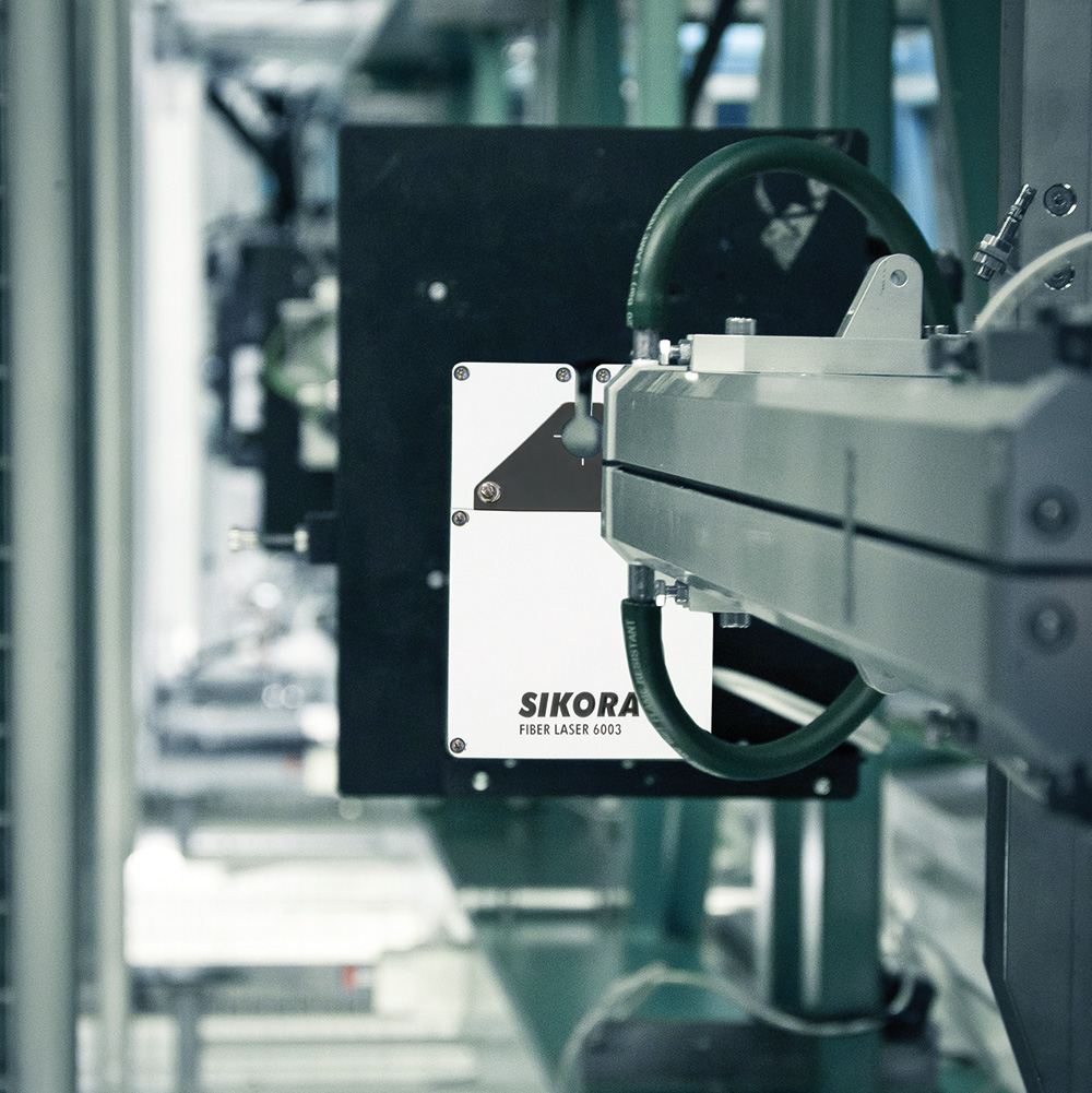
Typically, a first gauge head, the FIBER LASER 6003, is installed below the draw furnace to measure the diameter and position of the uncoated fiber. The gauge head calculates the tension from the vibration of the fiber with Fast Fourier Transformation (FFT). The single values of the fiber position are graphically visualized by the processor system FIBER ECOCONTROL in the form of a scatter plot and are available by ETHERNET. The LASER measuring process ensures a measuring accuracy of 0.05µm at a repeatability of 0.02µm. 2,500 measurements per second, with high single value precision and a short exposure time of 1.2µs, guarantee constant accuracy at the highest level.
Gauge head after cooling/before coating
A second LASER-gauge head measures the cold diameter of the optical fiber and the spinning after cooling and before coating. A control is done either by the hot or cold gauge head. Additional devices also detect airlines in the optical fiber and give information about the temperature of the optical fiber.
Gauge heads for the detection of airlines and measurement of the optical fiber temperature
There is a risk during production of the preform that air is being trapped and which, when drawn, becomes stretched air pockets, so called airlines. These airlines damage the quality of the optical fiber and, therefore, must be detected. Conventional diameter measurement devices can only detect the outer contour of the fiber but not the airlines inside. This is why SIKORA has developed the FIBER LASER 6003 AIRLINE. With 2,500 measurements per second, this device detects reliably, airlines in the fiber with a diameter from 0.5µm.
Before the acrylate layers are applied onto the fiber during the coating process, the exact measurement of the optical fiber temperature is important. In order to achieve an optimal bonding of the coating and the fiber, the temperature of the fiber should be between 40 °C and 75 °C. Manufacturers use the inert gas helium for cooling. The amount of helium that is used is calculated by means of experience. Often manufacturers use more helium than necessary to ensure that the fiber is not too hot for the coating. However, helium is a very expensive gas and, therefore, manufacturers of optical fibers want to reduce the usage to a minimum. At his position, SIKORA offers the FIBER LASER 6003 TEMP, which measures precisely and reliably the temperature of the optical fiber after cooling. With the information about the fiber temperature, the optical fiber manufacturer can use the exact amount of helium that is needed.
Gauge head after coating
After the fiber has received the coating and has gone through the UV drying process, a further FIBER LASER 6003 measures again the diameter of the optical fiber. After the coating, the diameter measures usually about 250µm.
Lump detection at the end of the drawing process
In addition to diameter measurement, lump detectors are used for a continuous quality control in drawing towers. After the coating and at the end of the drawing process, the 3-axis FIBER LUMP 6003 measures reliably lumps with a length of 500µm. Due to the growing quality requirements on the optical fiber market, SIKORA offers additionally the FIBER LUMP 6003 MICRO. The device detects faults from a length of 50µm on the optical fiber surface up to 100 %. This performance is achieved by the use of 6 measuring axes. Both gauge heads detect faults from a height of 5µm. Lumps are analyzed in regards to height, length, amount and position. All lump detectors feature the outstanding double sensor technology which ensures highest detection reliability.
Visualizing and controlling of production data
With the display and control system FIBER ECOCONTROL, the data of the connected gauge heads and lump detectors is displayed graphically on a 15” TFT monitor. A special control module ensures the continuous control of the diameter by controlling the line speed. Alternatively, a hot or cold gauge head is used for controlling (before or after cooling).
After the drawn fiber has been proof tested and wound onto reels, the fiber is being colored in a separate step and subsequently processed to an optical cable in a loose tubing or tight buffering line.
Conclusion
The integration of SIKORA measuring, control and testing technology in the optical fiber drawing process ensures a constant high quality of optical fibers. At different production stages the technology monitors and controls the entire drawing process and thus increases the efficiency of the production.


